Air quality and its composition, especially CO2-levels, are linked to complex problem solving performance, energy levels, and general health and wellbeing. With people spending large amounts of time indoors, it’s become critical that these spaces are well ventilated and supplied with sufficiently fresh air. Failing to do so will incur a non-trivial cost in lost productivity and an increased risk of adverse health outcomes.
This project aims to create a reliable, low-maintenance, compact, and quick-to-deploy sensor node for indoor use that leverages a single RJ45 connector for power and data transmission. Thus providing wide coverage of premises by integrating into existing network infrastructure.
The goal is to provide a reliable air quality profile, which will enable data-driven environmental optimisations. Ultimately leading to better air quality where and when it matters, while consuming less energy to do so.
The project repository can be found at GitHub.
Preparations
Component Selection
After the initial drafts of our requirements and other preliminary documents, it was time to do some component selection. At this early stage in the project my interest was squarely on the larger components of the sensor node, as they would be responsible for affording us the functionality to reach our requirements; and, also heavily influence our firmware and software development cycles.
Below is a brief table of my considerations:
- MCU
- nRF5340
- Support for Zephyr RTOS, and has all the required hardware units we need. Uses ARM, which all group members are familiar with.
- The recommended pairing for nRF7002 (Wi-Fi module).
- No reason to cheap out on the MCU for a few prototypes.
- nRF5340
- Power Delivery
- Power over Ethernet (PoE)
- This is an electrical consideration that I will contend with later. Reaching our firmware and software requirements first is more important for the project, so the data-side for the RJ45 will take priority. Magnetics come afterward.
- USB-C
- Including a basic connector for power, and maybe USB CDC ACM (UART-esque), is a good safety precaution that is trivial and cheap to implement.
- Power over Ethernet (PoE)
- Networking
- Wired (Ethernet)
- I selected the WizNet W5500 for the following reasons:
- driver support in Zephyr RTOS.
- breakout board from Adafruit.
- Power characteristics aren’t quite as good as some of the newest options from large players, but it’s close enough that reliable driver support, availability of application designs, favourable package format, and an accessible breakout sway the scales.
- I selected the WizNet W5500 for the following reasons:
- Wireless (Mesh | Wi-Fi)
- Matter over Thread or Wi-Fi would be good options to have, but due to limited time they may not be included in the final design.
- NRF MCUs have on-board support via the co-processor for Zigbee or Matter over Thread.
- nRF7002 DK can be used to reliably develop the Wi-Fi side.
- PCB-antenna?
- Backend
- We will target Home Assistant integration as the primary backend solution.
- The device will also quite predictably support pushing air quality metrics into an arbitrary URL.
- Wired (Ethernet)
- Sensors
- Carbon dioxide
- Volatile Compounds
- This category is more of an all-rounder, and should provide some generic information about the freshness of the air.
- A previous project I worked on used Bosch Sensortec’s BME690, and I still have a handful of those (couple already on PCBs), so this was a cost-effective choice that also meets our requirements very effectively.
- Carbon monoxide
- This is a little more tricky and may not entirely align with the idea for our device, as CO-sensors have a finite lifespan. Meaning the sensor would need to be swappable, which has an effect on the required interface (power, data).
- Some CO-sensors use digital interfaces (I2C, UART), others use Analogue outputs.
- Regulatory considerations are a very real concern with CO-sensors, and what can and should be claimed regarding the device’s ability to sense the compound.
- => Tentatively add a flexible interface for a CO-module (with I2C, UART, ADC-pin, GNDs).
- Particulates
- Another significant factor in air quality is fine particulate matter. Small particles in the air that when breathed in can cause reduced lung function, developmental issues, and sickness or allergic reactions with prolonged exposure.
- Things like dust, pollen, or organic compounds from burning reactions.
- I selected the Bosch Sensortec BMV080 for this role.
- Local Interface
- Buttons
- Generic buttons for navigating user interface.
- Reset switch for rebooting device.
- LEDs in some sort of configuration
- indicate power status
- indicate network status
- indicate co2 levels
- indicate general air quality levels
- Screen
- This isn’t strictly neccessary for a device like ours, but for the sake of learning we decided to include an eInk display.
- We picked a SSD1680 equipped eInk display from Adafruit, as there appear to be ready drivers in Zephyr RTOS. It also has convenient mounting holes we can use in our prototype.
- Buttons
Then we had a meeting with all group members, and affirmed that these were the parts we were moving forward with. Additionally, we decided to get two nRF52840 Dongles and one nRF52840 XIAO for development.
Development Kits
After the Digikey package came, I soldered all the pin headers for the MCUs and peripherals for use with breadboards during testing.
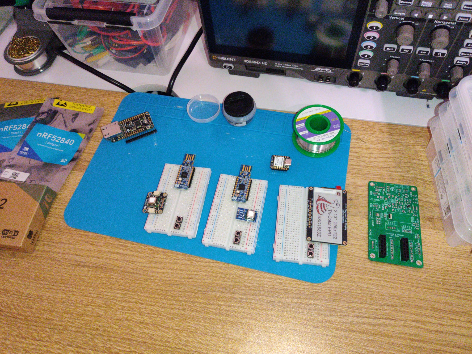
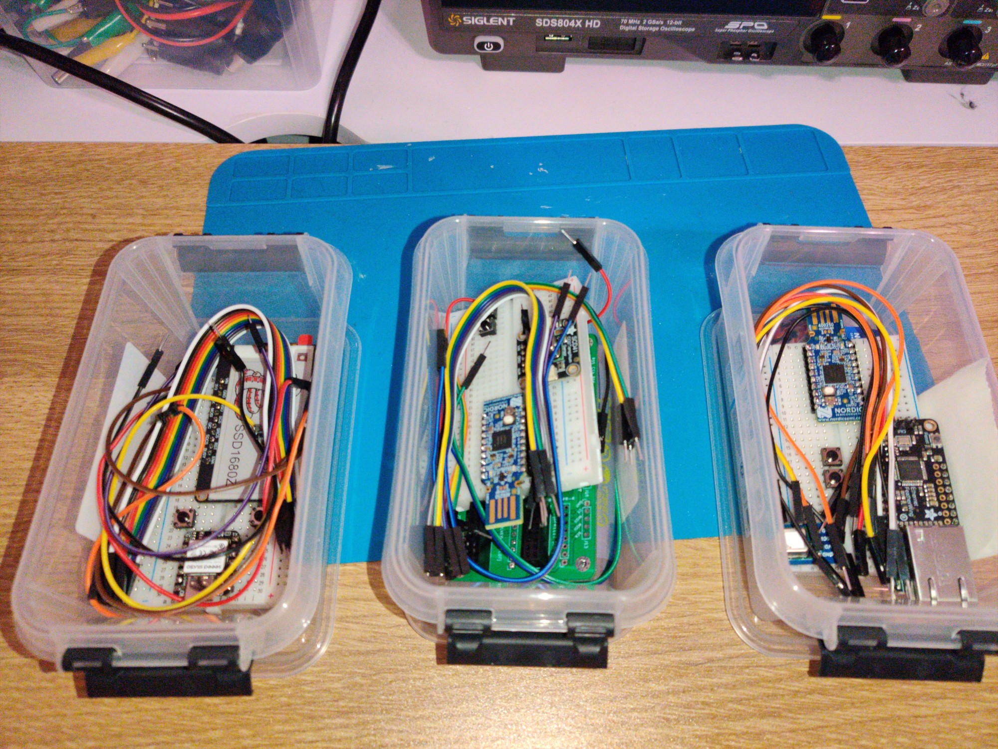
Once that was done, I packed everything into neat kits with some additional parts like a breadboard and an assortment of jumpers and buttons. This way I could give each developer a specific task to complete in firmware, and they’d have everything they need to do it without distractions.
- Kits
- 1: nRF52840 XIAO with eInk display (SPI).
- 2: nRF52840 Dongle with SCD41 (I2C), BME690 (I2C).
- 3: nRF52840 Dongle with W5500 (SPI), and SCD41 (I2C).
Source Control
We’ll be using a git repository hosted at GitHub, with a base structure that categorises sources based on the area.
 1/
 2├── README.md
 3├── electronic
 4│   │ # Schematic, PCB, BOM, Gerbers.
 5│   └── README.md
 6├── firmware
 7│   │ # C/CXX sources, unit tests.
 8│   └── README.md
 9├── mechanical
10│   │ # Enclosure designs and print files.
11│   └── README.md
12└── software
13    │ # Backend code for HA integration, WebUI.
14    └── README.md
We’ll be storing documentation in their appropriate sections within the README.md files.
The root README.md is reserved for general project documentation.