Baseline Description
This post details the current active configuration for my networks –both physical and virtual. Listed is the network structure and subnets, hardware choices and capabilities, layer 2 (L2) configurations, layer 3 (L3) configurations, and other network services and features.
This is the second in series of three and documents the IP-spaces and networks my machines reside in and take advantage of. Effectively providing the groundwork and platform for device to device communications for all my systems.
Goals
Layer 2
The objects for this layer are to provide strong segregation of subnets via port isolation and VLANs (802.1Q), high-throughput 10GbE trunk connectivity, 1GbE connectivity via access ports, and PoE+ (802.3at) for 30W of power for various IoT and security devices. The switches should not have any capabilities for Layer 3 routing!
Essentially, I need the L2 network to be as simple and infalliable as possible, low-maintenance, and performant enough to provide relatively high throughputs while remaining light on power consumption. The network was planned with 10GbE trunks and 1GbE access ports precisely because of efficiency targets (power usage, heat, cost). Increasing either trunk- or access port speeds would significantly increase power draw and cost for realistically very little practical benefit for my expected workloads and uses.
PoE is needed because the entire network and hypervisor will be powered from a single UPS. Using PoE will bring the downstream switches and their IoT and security devices within that envelope, so everything is power protected in case of outages or surges. There is an added benefit of reducing the number of needed AC-adapters which simplifies maintenance.
Below is an anticipated end-result of the VLAN zone assignments per router, and crucially the point-to-point links at L3. Some interface types have been labeled explicitly, so the depth of the networking is more apparent at a glance.
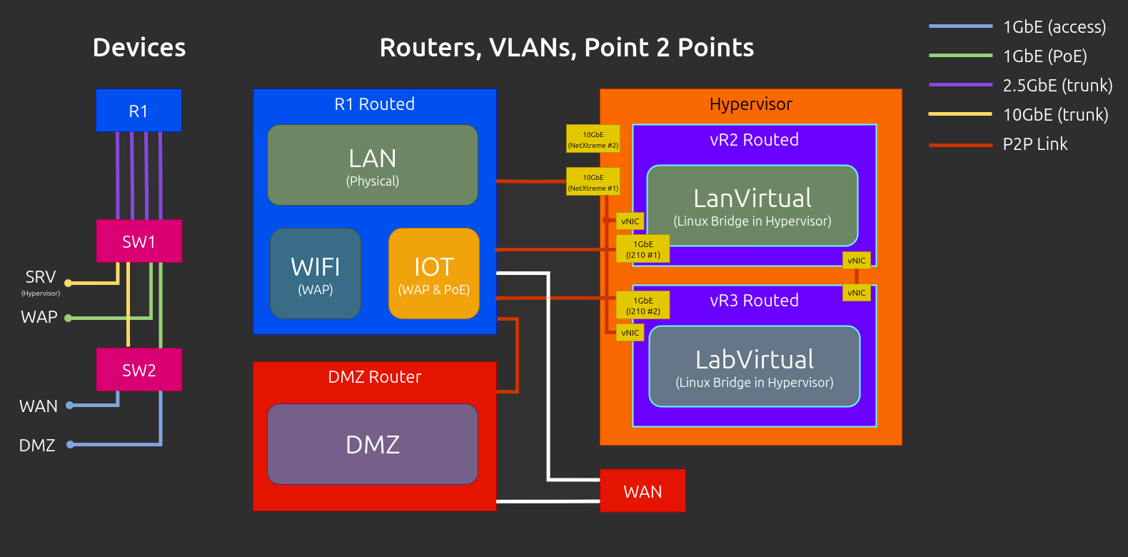
Note that the Hypervisor’s internal bridge layout is simplified in the previous graphic, and doesn’t fully reflect reality. There wasn’t enough space to label and display everything in a way that didn’t make the graphic too busy.
Layer 3
For my primary router I want a dedicated machine. While I technically have the option to virtualise it, I’m kind of past doing that for my primary gateway (see historical). I need routing, dns, and network time to be reliably available; and, as unaffected as possible by other upgrades and maintenance.
The router will need to provide sufficiently fast inter-vlan routing relative to my 10GbE trunk connections, enough processing power to encrypt and decrypt multi-client VPN traffic (OpenVPN and Wireguard), flexible firewall rules, policy-based routing rules for multiple gateways, and on-device certificate management and load-balancing for basic services.
The router should also provide at least local DHCP, NTP, DNS, TFTP, and limited IP and DNS-blocking capabilities.
Hardware Choices
Switching
For my L2 network I chose to go with Mikrotik switches. In part for their excellent price-to-performance and sensible SKUs, and in part because they have a long-standing reputation for good reliability and support among the enthusiast and professional space. They’re also based in Europe, which is great because I get to support an European company.
Specifically I chose the following two switches:
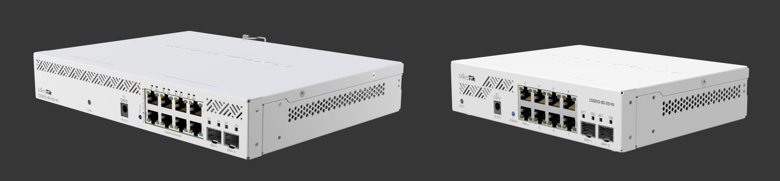
- Main L2 Switch (SW1)
- CSS610-8P-2S+IN
- SwitchOS Lite
- L2 features only
- Dot1q VLANs, MAC filters, MAC-IP headers, traffic mirrors, bw limits, …
- PoE monitoring (Current, Voltage, Power)
- 2 x SFP+ (10GbE Copper or Optical)
- 8 x 1GbE (with PoE+ out)
- 12 Watt w/o attachments
- 160 Watt PoE budget
- Secondary L2 Switch (SW2)
- CSS610-8G-2S+IN
- SwitchOS Lite
- L2 features only
- Dot1q VLANs, MAC filters, MAC-IP headers, traffic mirrors, bw limits, …
- PoE monitoring (Current, Voltage, Power)
- 2 x SFP+ (10GbE Copper or Optical)
- 8 x 1GbE
- Passive PoE input for power
- 5 Watt w/o attachments
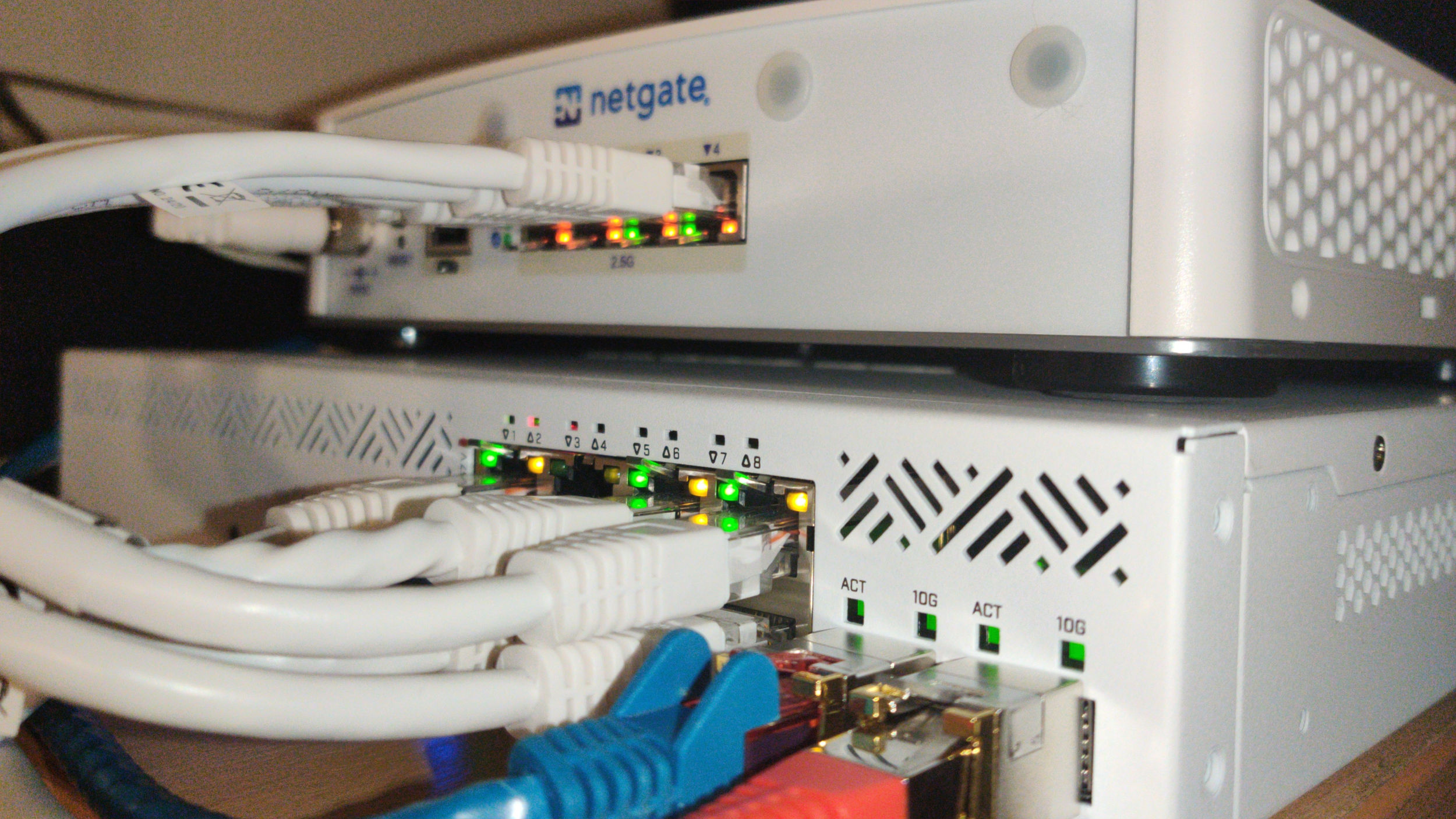
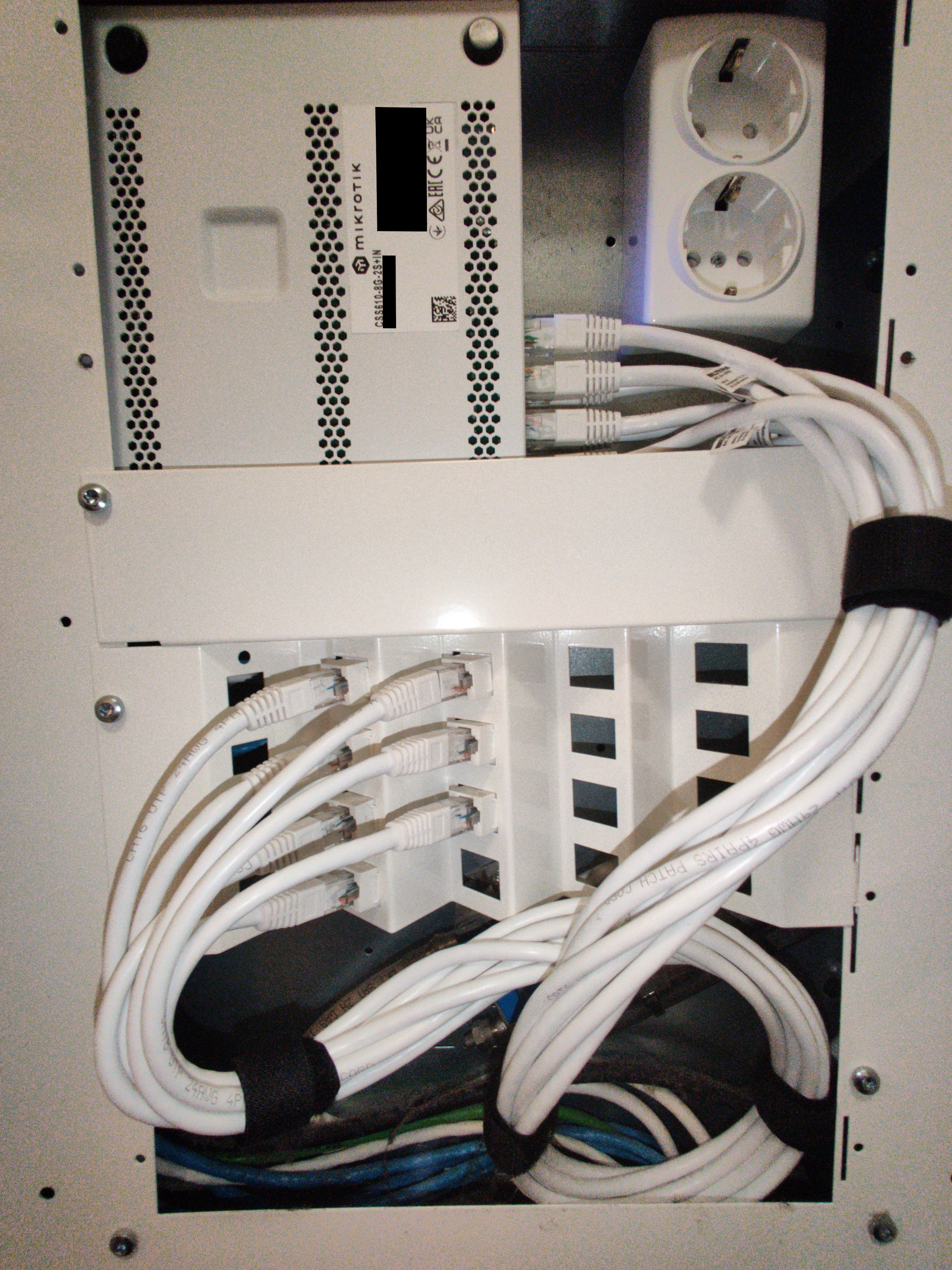
These switches are effectively the same product, with the difference being one has PoE+ outputs and the other can be powered via its PoE input. The unit without PoE outs is also conveniently much smaller, so it can fit into a small patch panel as seen from the photo below.
Note that the loads in the cables below will be low –just that one PoE input to SW2. So the very convenient loop pictured in the photo won’t be melting anything in its vicinity or causing other trouble… But yes, it’s indeed bad practice to make loops like that. I just got fed up with the cables pushing the panel door open.
Another notable choice for the L2 network was the SFP+ modules I use for the trunk links. Due to what is in-between the walls and what NICs I have available on my hypervisor, I had to use 10GBASE-T on my SFP+ ports. Optics or DAC would’ve been more efficient financially and thermally, but neither was an option in my case.
I initially purchased two Mikrotik branded SFP+ modules; and, while they work great they’re also based on older (Marvell?) chips that use a lot more power. The downside to using more power is critically the additional heat, and below is an example of just that.

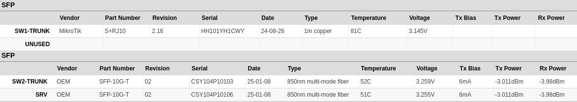
Firstly, we can see that having two of the newer modules side-by-side in SW1 yields temperatures around 50-54 Celsius, while the single older variant SFP+ module from Mikrotik hovers in excess of 80 Celsius when on its own. Both SW1 and SW2 chassis are passively cooled and have no fans circulating air. This temperature difference is enormous, and I would readily replace the Mikrotik module if the 80 meter 10GBASE-T modules didn’t cost 70€ a pop (ouch…).
So if you’re in a spot where you must use copper, and a DAC isn’t an option, make sure you get the newer Broadcom chipped modules. Look for something with BCM84891L in it, though you may have to take someone’s word on it. When I was looking, it was difficult if not impossible to find indication on the chip in product listings. Look for brands that other people online have verified to run cooler and behave well in use, and make sure the listing indicates the module is for either 80 or 100 meters. The support for longer runs indicates a more efficient model!
This is what I bought, and what works well for me, but it’s practically for 10Gbps only!
Routing
For my primary router I chose to go with a first-party pfSense router from Netgate. Its specs are strong but modest. It doesn’t provide any crazy unique connectivity or features, and the RAM is soldered, but it’s all low-power, has a well balanced specsheet, and uses reliable parts.
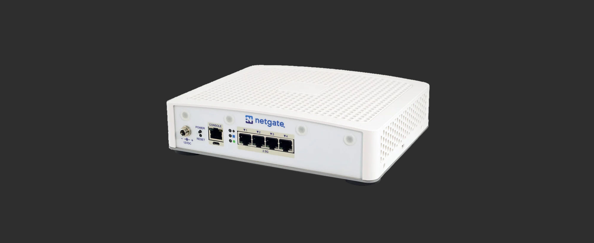
- Netgate 4200 BASE
- Software: pfSense+ included
- CPU: Intel Atom C1110 (x86, 4 cores, 2.10GHz)
- RAM: 4GB LPDDR5 (5200 MT/s)
- DRIVE: NVME drive (M-key), and internal eMMC (shouldn’t be used, design mistake!)
- Console ports (“Cisco pinout” RJ45, micro-USB)
- PORTS: 4 x 2.5Gbps unswitched Ethernet
- Speed (L3 Forwarding): ~9Gbps
- Speed (Firewall, 10k ACLs): ~8Gbps
- Speed (AES-GCM128 w/ AES-NI): ~3Gbps
- Power consumption: ~13-20 Watts
I’ve been using pfSense since 2018 as my primary firewall and router OS, so I knew it serves my needs well. As to why I selected a first-party router that comes at a price premium…
pfSense (CE) is Free & Open-Source software (FOSS), but its existence and continued availability should not be taken as a given. As I’ve had the privilege of using it free for many years since I initially virtualised it back in 2018, and have used it ever since. I feel it was only fair to kick back a little thanks for all that time and opportunities to learn and tinker, even if in the grand scheme of things it counts for very little.
Additionally, as efficiency was a key part of my design, I specifically wanted a low-power machine. I couldn’t just use an old computer because they tend to draw a lot more power, specially when kitted with the neccessary NICs. This is why I selected from the purpose built routers on the market.
For anyone considering a new router, I would really urge to consider if it’s a smart choice to buy a no-name chinese router as your primary firewall and router. This is the device that sits between all your networks, data, machines, and the internet. For a modest amount more you could have something from an American or European company securing your network with reliable documentation, while also kicking back a little support for the projects they advance and maintain for the benefit of all. If Netgate’s models are outside of your budget or needs, Mikrotik makes some very good budget friendly routers that use their RouterOS!
Software and Configuration
This section is split into three categories: switch configuration, router configuration, and service configuration. I won’t go over the exact configurations I apply on my network for some practical and security reasons, but I’ll instead substitute in some generally applicable settings where needed so I can illustrate the available functionality for each section.
Switch Configuration
Mikrotik SwitchOS Lite
The objective is to limit the physical L2 network so that ports are segregated into their own forwarding domains. There are two main ways of accomplishing this in Mikrotik’s SWOS Lite, port isolation and VLANs.
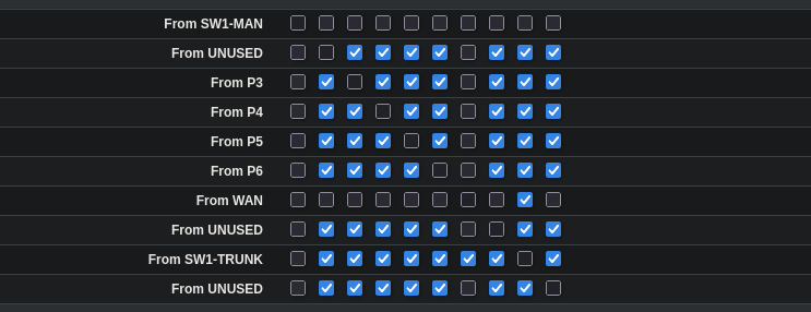
Port isolation is a way to limit frame forwarding between the ports on the switch. You could imagine this as “disconnecting” individual ports from each other, making sure no frames can travel between devices on ports that are isolated from each other. Below is a simple example where the inbound WAN link is isolated from everything except the trunk that is heading towards the primary switch and router.
Note that some more complex Rapid Spanning Tree (RSTP) configurations may struggle with specific port isolation setups. My topology is simple enough that I don’t need to worry about loops. Refer to Mikrotik’s documentation for more information on the limitations and gotchas.
The access ports could further be isolated from each other by only permitting forwarding to the trunk link. This would effectively mandate local firewall rules between the isolated clients at the cost of additional latency and extra processing load on the router. Inter-client communication would also then depend on the router being online.
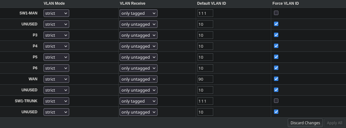
VLANs will be used to divide the physical switching domains virtually by an ID. This is just the regular Dot1Q spec that can be found on basically every managed switch nowadays. The following is a small example of VLANs for: LAN (10), WAN (90), and default catch (111) on trunks to combat vlan hopping.
With that, most of the setup for L2 is complete. The remaining steps include locking down some features and restricting access by: turning off SNMP, restricting management to specific ports, disabling mikrotik discovery protocol, and configuring DHCP Snooping to only trust the appropriate upstream ports.
Router Configuration
I currently use both pfSense and OPNsense on the network. My primary (physical) router uses pfSense+, while the virtualised routers use OPNsense. I’ll cover the fundamentals with pfSense, because the configurations are mostly identical on OPNsense, the only real difference in configuring them is the slightly different UI and menu structure.
The basic L3 configuration I’ll be covering includes: effective aliasing of ip-blocks and ports, firewall rules, policy-based routing, point-to-point routes, securing upstream dns queries, network time setup, and basic dhcp pools.
pfSense
Defining Aliases
Before configuring anything on the router, I prefer to do some groundwork and setup sensible alias lists. This will make managing different rulesets across subnets vastly more straightforward, as a set can be applied on an as-needed basis to a network. Editing is then done via the central alias definition, and the changes are applied to all the associated subnets automatically on reload.
Let’s suppose you want to control the use of EMAIL to users inside a subnet. You could define a simple alias definition for PORTS that references 465 (SMTPS), 993 (IMAPS), and 995 (POP3S):
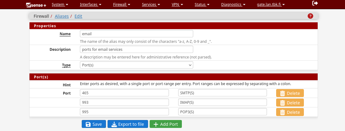
Now you can simply reference the name “email” when controlling these port(s) inside your firewall rules. This is a vastly more robust method of managing rules that reduces the risk of configuration errors, while cutting down on the amount of labour it takes to manage more granular rules for multiple subnets.
Firewall rules
By default pfSense uses the industry standard of default deny to all inbound and outbound traffic. This means that for traffic to be routed, you must specifically PERMIT it by setting up a rule. Do note that any traffic that doesn’t need to cross IP-space boundaries is not controlled by these rules (e.g. switching domains at L2). So if the machines are in the same physical L2 subnet, they can always talk to each other unrestricted by the router-level firewall rules as long as the switch ports aren’t isolated.
When creating a rule, the following fields can be specified:
- Firewall Rule Fields
- Protocol
- Source Addr.
- Source Port
- Destination Addr.
- Destination Port
- Gateway
- Queue (traffic shaping)
- Description (administrative reference)
Most of these fields are self-explanatory, so a quick practical example should be enough to illustrate setting a rule:

The above rule is a PERMIT type rule (green checkmark) that allows IPv4 TCP and UDP traffic from the “GW_WIFI” subnets to any destination IP that matches a port speficied in the “applications” alias list via available routes specified in the “WIFI_GATEWAYS” list.
To put it more plainly: Clients in the WiFi subnet are allowed to use “applications” residing on any target IPv4 subnet (including internet), but only via a route defined in “WIFI_GATEWAYS”.
Gateways and Policy-based routing
In the previous firewall example I had configured the rule to use “WIFI_GATEWAYS” as a permitted route for the specified traffic. It’s an optional field that can be attributed to a rule to control what interface the outbound traffic is allowed to take. It’s only relevant if you have multiple WAN addresses, or need/want to very specifically dictate what static routes are used for local traffic.
The configuration interface for gateways in pfSense is a little confusing, as there are multiple unique views of effectively the same settings. The configurator is also very picky about deletion and renaming of existing gateways and gateway groups due to some backend inflexibilities. I’ve found the best view to configure the gateways is the one depicted below:
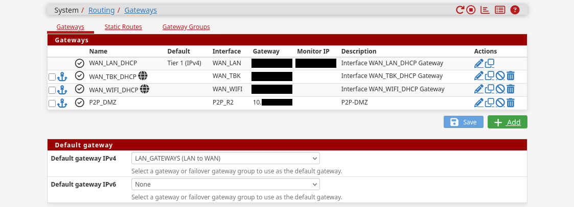
In my example I’ve created four gateways: physical lan to internet, wireless clients to internet, tbk to internet, and a local point-to-point route to the DMZ subnet. It’s possible to further create groups of these gateways in the “Gateway Groups”:
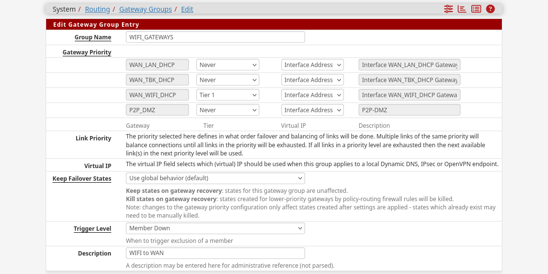
This way you can specify fallback interfaces in case links go down, latencies spike, or packet loss increases above tolerable levels. Setting multiple gateways active at the same tier will load balance traffic across them.
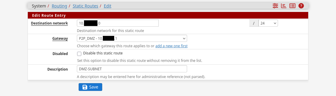
Point-to-point Routes
Static P2P routes can be setup in the same gateways interface that is visible in the previous pictures. All you have to do is first create an appropriate gateway for an interface, then tie that gateway into a destination network in the ui. This should be enough to create the neccessary routes on the system.
Secure DNS queries
Setting up properly encrypted DNS queries for the network in pfSense isn’t as simple as defining the appropriate server addresses and TLS hostnames. It’s important to also explicitly block unencrypted queries via port 53, and verify through diagnostic tools like pfTop that no unencrypted queries are slipping through during use.
The first step is to define the desired DNS servers and their TLS hostnames in the general setup tab, and to instruct the router to ignore any upstream offerings:
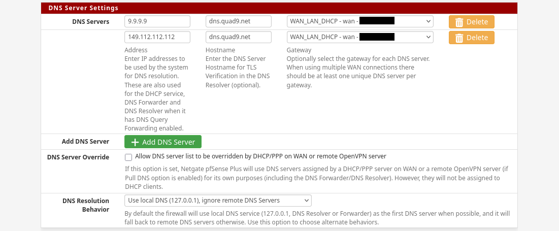
After defining upstream DNS servers for the system, it’s important to change firewall rules so that unencrypted DNS queries aren’t permitted to the internet. If DHCP is used for subnets, it’s also a good idea to to offer the router’s IP as the DNS server with DHCP leases. Some more dumber devices may need to be manually configured.
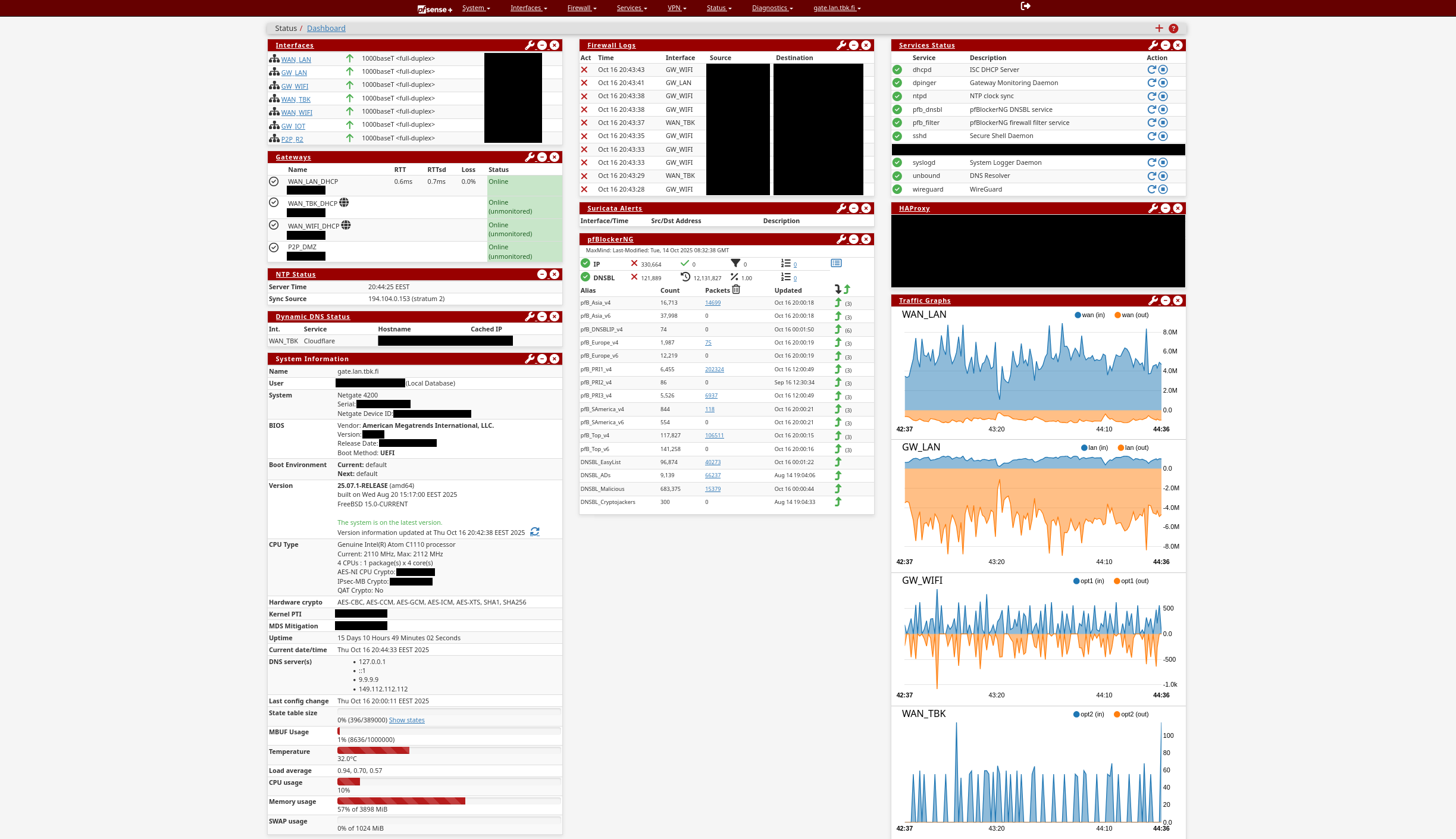
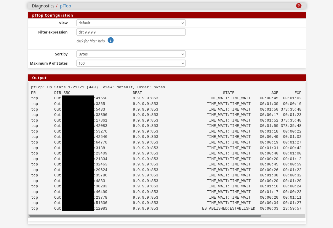
Lastly it’s important to verify that the settings actually stuck, and do what is expected. The “Diagnostics” menu has a view for pfTop, which can filter based on destination address or port. This allows inspection of active connections, making it easy to verify no traffic is traveling via port 53. If all is well, the view should be similar to the following example:
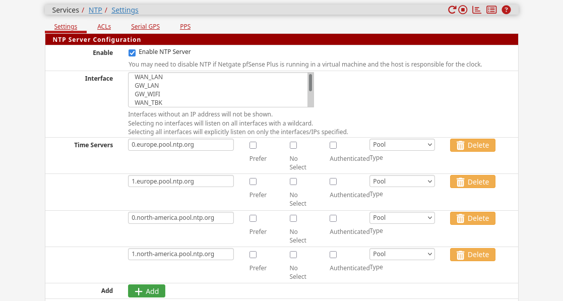
Network time
Setting up pfSense as an NTP client and server is trivial. Just define the desired upstream NTP time servers or pools, make sure the clients on the network ask pfSense for time, and that the firewall rules permit NTP traffic (port 123) to the gateway on the internal interfaces.
A list of public ntp pools for use can be found at ntppool.org.
DHCP-server and pools
Each interface (physical and virtual) can be configured with its own DHCP pool and unique settings. The interface automatically defines the permitted subnet range through the subnet mask, so all that needs to be done is set the pool start and end addresses.
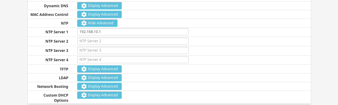
Additional commonly configured settings include providing: default domain, NTP server address, DNS server address, TFTP server address, and LDAP server URI to the DHCP clients. All of these settings and more can be configured from the interface-specific DHCP server view:
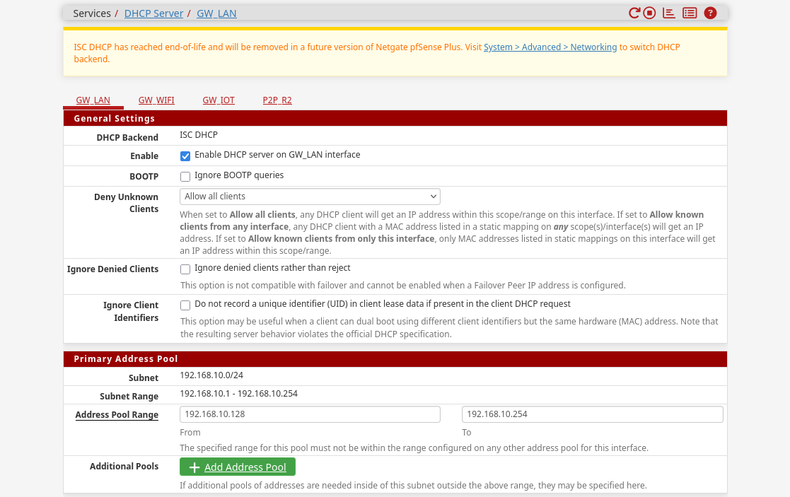
As of writing, the migration from the legacy ISC DHCP server to the new Kea DHCP server is ongoing. I’ve had bad experiences with Kea crashing and getting stuck very frequently, requiring manual intervention, which is why I still haven’t moved to the new backend.
OPNsense
Currently unneeded, refer to the pfSense section. May be updated in the future if enough deviation from pfSense sections.
Service Configuration
For the sake of convenience I like to host some basic services on the main router itself. This makes certain things a little easier to manage, and in general makes sure that I don’t accidentally nuke crucial network features when messing around with the other servers or hosts on the network. This isn’t a good strategy for performance and security related reasons on a bigger network, but for my home-lab uses its preferable.
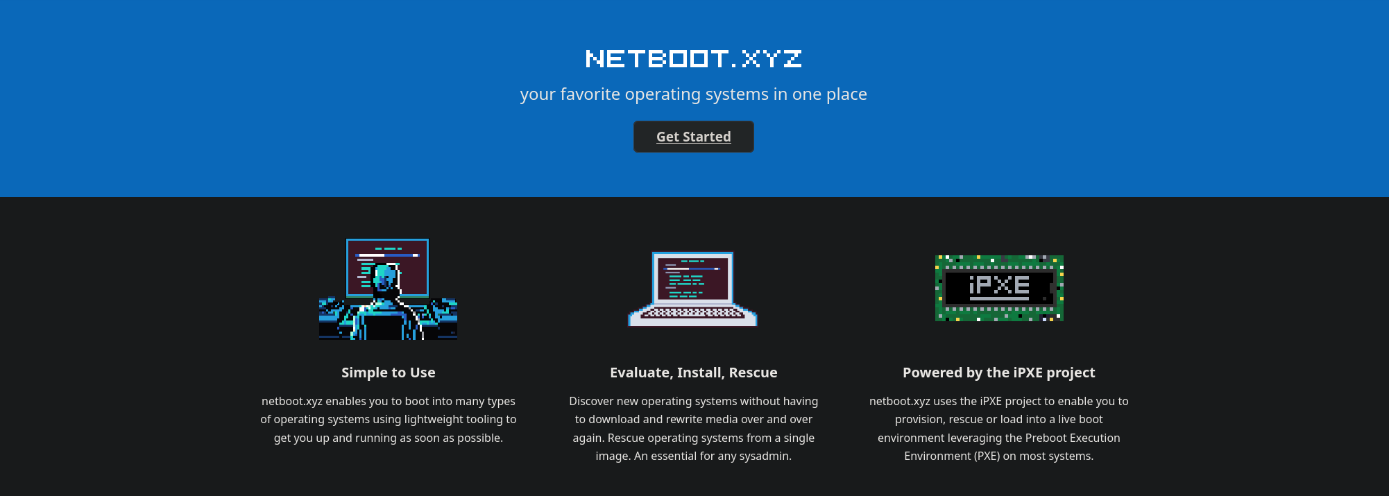
TFTP
Installing the TFTP-server package allows hosting something like netboot.xyz on the pfSense machine itself. It’s useful for providing an easy network-booted PXE environment for clients.
I use it at times to install a new OS onto a machine without the need to hunt for a USB drive and flash the ISO to it, or just to test some hardware without committing a disk for the short duration of the test(s).
Wireguard
Putting a Wireguard server on the pfSense box is an easy way to make sure the server is always online. This also allows it to better be integrated into the existing network structure, making management of routes, firewall rules, and other network details more seamless.
The tools available in pfSense aren’t as great as some other solutions for wireguard, even something like simple dockerised wireguard server containers, because some of the quality of life features are missing. For example, if you want QR-codes of the profiles, you’ll have to manually download the configuration and use a tool like qrencode to make them yourself.

HAProxy
I like to terminate my certificates at the main router, which is why I also prefer running HAProxy on pfSense. This allows me to centrally manage certificate renewals in one place for the internal networks, and also implement observability after termination at a couple points in the secure and isolated internal subnets.
Setting up a simple HAProxy instance has two parts, first setup the backends that point to the correct server(s) the service is running on. Secondly setup the frontend that matches inbound connections to ACLs which route the requests to the correct backend. I’m not in the mood to go over the whole process here, so refer to the official documentation for guidance.
I will say, that the HAProxy package in pfSense is flaky during setup. Sometimes the entire pfSense machine has to be rebooted/rerooted for setting changes to become active. It’s apparently an issue with some file locks not correctly refreshing on service restart. This is a long-standing issue, so who knows how long it’ll continue to cause issues for. Regardless, after setup things have been solid for years in my experience. It’s just a pain to debug because the behaviour is unreliable during configuration updates.
Ntop
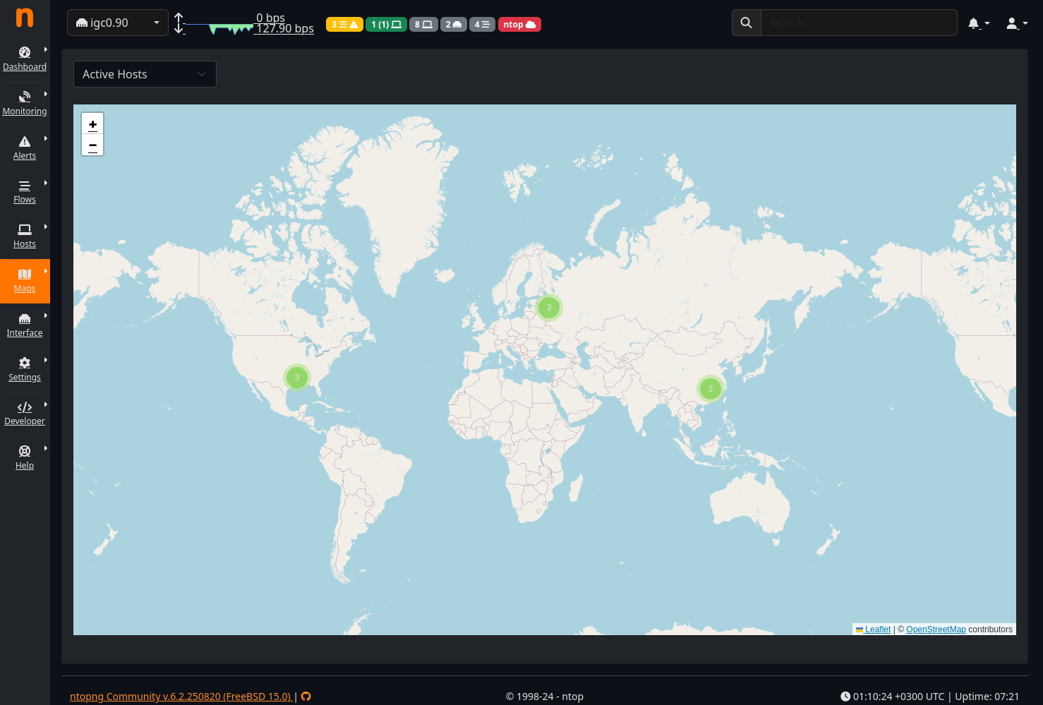
Ntopng is a “High-Speed Web-based Traffic Analysis and Flow Collection” tool that provides fancy graphs and lists of network devices and connections. It’s good for general mapping of the network when you want to take a closer look at things, or monitor more critical networks for changes and data flows. It therefore benefits from being installed onto a central location in the network to have full access to the relevant subnets and interfaces.
Note: After installing the package, its settings and webui can be found, confusingly, under the “Diagnostics” menu, not the typical “Services” menu in pfSense.
Running Ntopng is quite RAM intensive in my experience, so maybe consider using it intermittently for statistics if the machine doesn’t have a lot of RAM available. If resources aren’t an issue, it can be left on 24/7/365 and configured to send out notifications when defined environment changes happen, which can be very useful depending on the context. The program can also do basic kind of inference from network data to determine what kind of traffic (or application) its seeing. Though TLS makes this vastly more difficult nowadays.
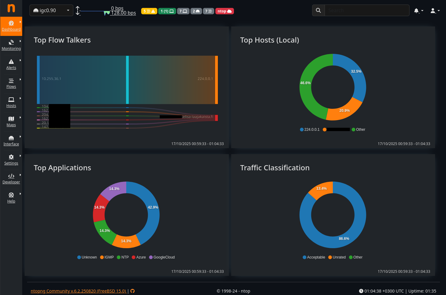
If you keep the program on consistently, you can also benefit from the nifty map view to see where flagged connections originate from. Below is a quick example of the logged inbound WAN connections on VLAN ID 90 (igc0.90) for the past ~30seconds:
Clicking on a flagged cluster and selecting a specific host further shows details on its status as either a client or server:
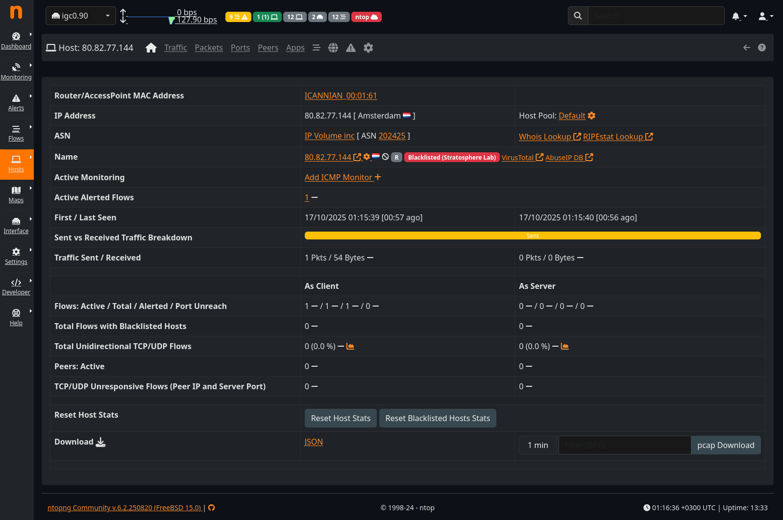
In this case this specific host (located in Amsterdam, NL) has been flagged by a trusted blocklist, which is why its data flow was marked.
Suricata
Suricata is an incredibly complex and capable Open Source network analysis tool. I’m not qualified to go into detail on its operation principles at scale, and to properly configure it depends heavily on the active environment and applications being ran in it. Nonetheless, it’s a great tool to play around with to learn more about observability, IDS/IPS, and how programs communicate and what data flows in a network.
It can be setup to react to specific data or queries being passed to servers among other things, and provides the ability to write custom actions based on the used rulesets. You can imagine that being able to, for example, monitor all passed queries to a database server alone provides a lot of powerful options for monitoring and enforcement. If you know how a program communicates, and can give Suricate visibility into that communication, you can write your own rulesets and relevant actions.
Historical
From 2018 to early 2025, I virtualised my main router (among other things) on single valiant Intel NUC8i5BEH. The setup was all about efficiency in power consumption, cost, and heat/noise output. By the end I had modded and added plenty of small improvements to the configuration. Perhaps my favourite being the passive cooling case, which while expensive, made the entire machine fully silent, removed dust from the equation, and improved cooling massively from the anemic stock fan. The improved cooling unlocked even more potential for me to stuff VMs and containers into an already bursting-from-the-seams frame.
The setup served me better than well for many years with rock solid stability. I did a lot of things people online explicitly advice against, and in doing so I saved a lot of money on the initial investment into hardware and the continued operating costs.
It was however a very complicated setup to spin up from a faulted or otherwise offlined state. There was a very specific song and dance that had to be performed each time the base OS was updated or restarted. A single wrong move and everything stalled, because a lot of machines depended –one way or another– on the various network services to be available at startup. Not to mention, if that machine couldn’t come online, the internet was down for the whole home!
So it was time to upgrade… Here’s the last photo of the complete old setup during the migration to the NG4200.
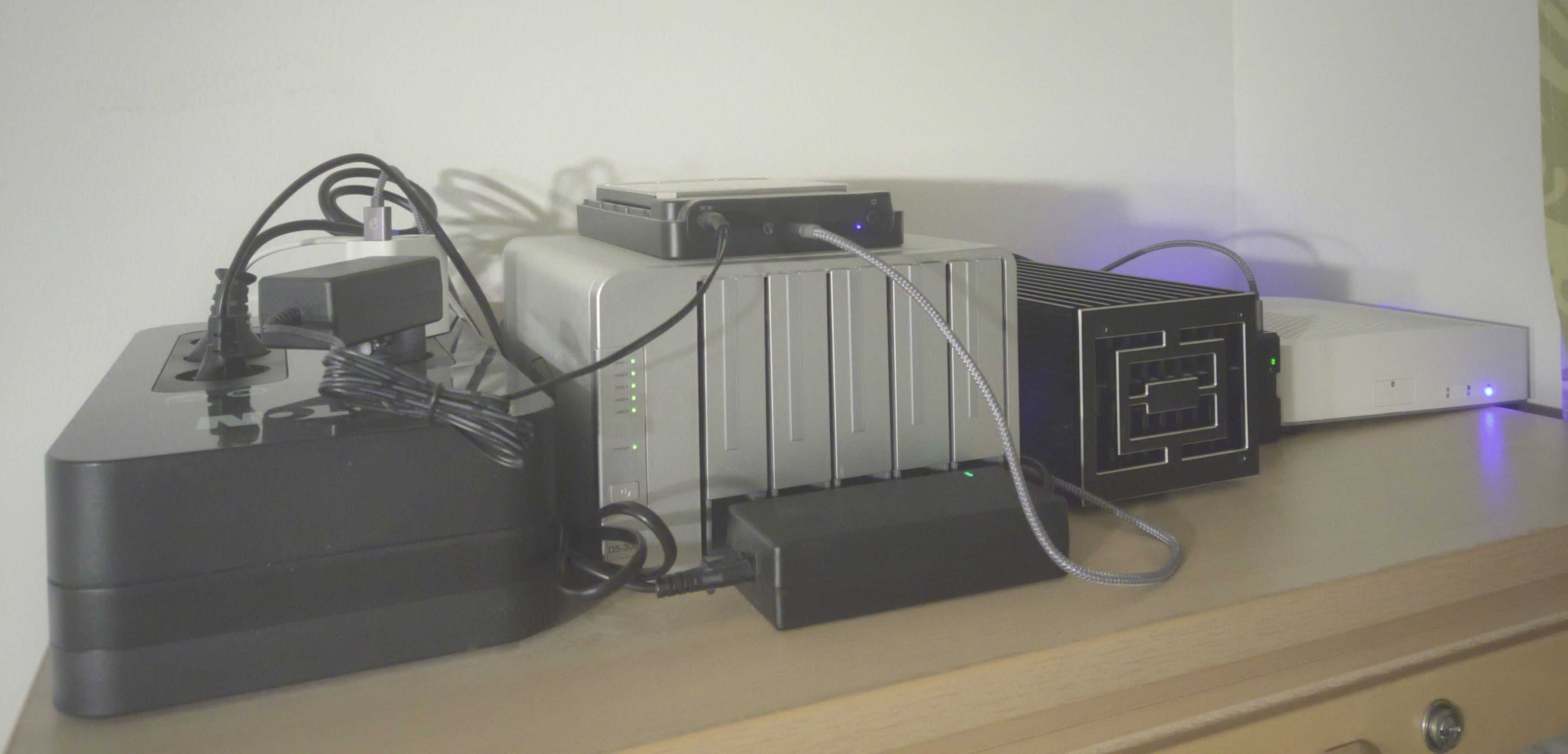
Pictured in the photo from left to right are: Eaton UPS, 5-bay USB DAS for HDD disks (plus a 10TB disk on top as scrap storage), the Intel NUC in its aftermarket metal case, a small Raspberry Pi 5, and the new NG4200.
As for the old switch I used? It was the cheapest 15€ managed Gigabit switch from the local store, and its still running!
Wrap-up
I think I covered most of what I needed and wanted here. The remaining last baseline post will go over the other inherited functionality from the old Intel NUC based setup.
The old King is dead. Long live the King!